Ti:Sapphire crystal cutting process
Orient the crystal→ Select crystal blank with high quality → Glue blank → Cut blank→ Brewster angle cut→ cleaning
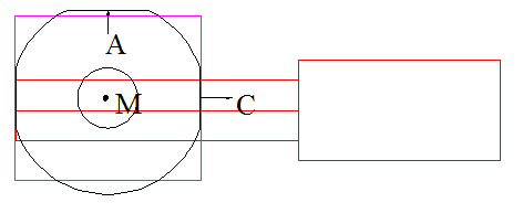
1)Set M Direction:
The unusable part (with more air bubbles and grain boundaries) at the top of the crystal blank along the M direction should be roughed and removed with a single-axis machine. During this period, the crystal direction should not be deviated to facilitate the orientation. After fine grinding and orientation, the orientation accuracy is within 10′, the seed crystal at the bottom of the crystal is removed, and then the bottom conical part is ground to a thickness of 10mm according to the above process. Note that the deviation of the M-direction angle should not exceed 10′.
2)Set C Direction:
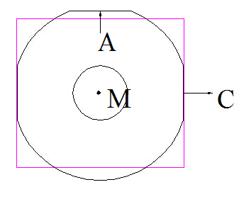
Due to the particularity of the crystal, the A-direction and C-direction of the crystal grown in the M direction are both on the side surface, and the three directions of A, M and C are perpendicular to each other. Find the C direction according to the orientation data of the PDF card. Observe the C direction under the stress meter. During the rotation along the vertical C plane, the brightness of the light does not change significantly on other surfaces. When the C direction is found, the C direction is oriented according to the process of a, and the orientation accuracy is less than 10′; afterwards, the A surface is ground out, and the orientation accuracy is less than 10′.
3)Select Material
Polish the C surface of the crystal after the above fine grinding. After polishing, check the internal quality of the crystal (grain boundary and stress). If the crystal quality is intact, select the size of the blank according to the requirements and proceed to the next step;
4)Glue Blank
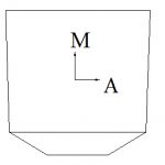
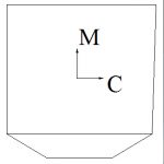
Wipe the above-mentioned ground crystal on the M side and C side and place it on a heating furnace for heating. The temperature rise rate can not be too fast. According to the method shown in Figure 1, first bond the M surface and the glass with shellac and rosin glue together. The glue should be spread evenly, and there should be no bubbles between the crystal and the glass; heat the material board with a lamp until the shellac It can be melted on the material board, spread the shellac evenly on the material board, and then bond the crystal and glass that have been bonded before to the material board according to Figure 2. The details to be paid attention to in this process are: end face C surface should be parallel to the edge of the material board. After bonding, place it on a flat position and fix it, so as not to shift the crystal.
5)Cut Blank
Glue the crystal according to the above method, install the tool holder and use a right-angle knife to calibrate the knife. The knife should be accurate and the limit should be set. The C surface on the right side is parallel to the knife edge. Note 1: Before cutting, the orientation of the slice should be adjusted, and the angle deviation should be adjusted. The position of the first cutting knife is on the right side C surface parallel to the knife surface, and the knife exit is 2mm. The thickness of the first piece is about 1.5mm. Take off the piece and adjust the angle if there is any deviation.
After opening the material according to the above process, open the square strip with adhesive material, reserve a margin according to the size of the finished product, and orientate the finished product before cutting. Note: When sticking the material, the polished M side faces up, which is convenient for tool setting, and the C side sticks the material. At the same time, for the M and C sides, the knife should be accurate and the limit should be set. Before cutting, the slice should be oriented. The slice thickness is less than 2mm. If there is a deviation in the orientation, use the laser to adjust the angle until the deviation is less than 10′.
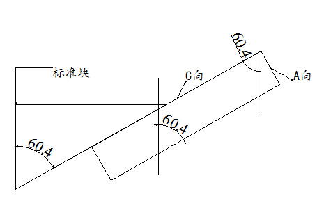
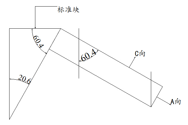
6)Brewster Angle Cut
There are two ways to cut the Brewster angle. If the end face is not marked in the A direction (the A side is not oriented, the M direction and the C direction are standard), the first method is to stick the material to the knife. If the three directions of ACM are all standard surfaces, you can cut in the second way. When the finished product is square, you can directly cut out two bush corners, leaving a polishing margin of 0.5mm; if the finished product is round, and one bush corner, then send out rounding, pay attention to protect the Brewster corner during the rounding process.
7)Cleaning
Roast crystal after cutting process, Wipe the oil and glue on the surface off, Cool wafers naturally. Polishing wafers if it is required.